Tuesday, March 25, 2008
Software Updates
FortiOS 3.0 MR6 Patch 1 is available for all Fortigate platforms and the Fortimanager appliance. Also FortiOS 3.0 MR5 Patch 5 is available for the Fortigate platform which includes some minor bug fixes over MR5 Patch 4..
Session Timeouts
The Fortinet platform like most other stateful firewalls keeps track of open TCP connections. Each established session is assigned a timer which gets reset every time there is activity. If the timer expires due to inactivity the session is removed from the firewall tables and you will have to re-establish the connection. The session can also be cleared without waiting for the timer to expire if the firewall sees a FIN or RST packet for a given session.
Imagine you have a telnet connection on port 23 to a server in your DMZ. There is a script which executes periodically to poll some data using the telnet session. You notice that when the script hasn't executed in 60 minutes the telnet session is lost and you have to re-establish the session.
The easy answer is to increase the session ttl (time-to-live or timeout). This can be done on the CLI on a global basis for all ports or only for specific ports. Keep in mind that raising the timeout values for all ports can significantly increase the amount of system resources (especially RAM) consumed. This is due to the fact that the firewall now has to potentially keep track of the same number of sessions for a longer period of time. The default value of 60 minutes/3600 seconds should be ok for most applications.
The following example sets the timeout value for all TCP services to 3000 seconds but increases the timeout for telnet (port 23) to 7200 seconds.
config system session-ttl
set default 3000
config port
edit 23
set timeout 7200
next
end
end
DHCP Address Reservations
If you use the DHCP server on the Fortigate you can configure DHCP address reservations to always assign specific IP addresses to a computer, based on its MAC address.
Use the CLI command config system dhcp reserved-address to reserve an IP address for a particular client identified by its device MAC address and type of connection. The DHCP server then always assigns the reserved IP address to the client. The number of reserved addresses that you can define ranges from 10 to 200 depending on the FortiGate model.
Use the CLI command config system dhcp reserved-address to reserve an IP address for a particular client identified by its device MAC address and type of connection. The DHCP server then always assigns the reserved IP address to the client. The number of reserved addresses that you can define ranges from 10 to 200 depending on the FortiGate model.
Use the following syntax to always assign 192.168.1.1 to the device with MAC address 00:04:f1:11:11:11.
config system dhcp reserved-address
edit "ip_phone"
set ip 192.168.1.1
set mac 00:04:f1:11:11:11
next
end
edit "ip_phone"
set ip 192.168.1.1
set mac 00:04:f1:11:11:11
next
end
In FortiOS 5.x use the following syntax
config system dhcp server
edit 1 (or other number as appropriate)
config reserved-address
edit 1
set ip 192.168.1.1
set mac 00:11:22:33:44:55
next
next
next
edit 1 (or other number as appropriate)
config reserved-address
edit 1
set ip 192.168.1.1
set mac 00:11:22:33:44:55
next
next
next
end
SIP and H.323
If you run into problems with SIP and H.323 traversing your Fortigate firewalls this may be related to the SIP and H.323 session helpers (i.e. proxies). You can tweak them on the command line only. Here is what a typical configuration looks like:
config system session-helper
edit 1
set name pptp
set port 1723
set protocol 6
next
edit 2
set name h323
set port 1720
set protocol 6
next
edit 3
set name ras
set port 1719
set protocol 17
next
*** snip ***
edit 12
set name sip
set port 5060
set protocol 17
next
edit 13
set name dns-udp
set port 53
set protocol 17
next
end
To disable the SIP and H.323 session helpers use the following syntax:
config system session-helper
delete 12
delete 3
delete 2
end
Keep in mind to delete session helpers starting at the highest numbered one. Otherwise you may inadvertently delete the wrong session helpers if you are not careful.
*****
Update: In FortiOS 3.0 MR6 and above you should also try the following commands:
config system settings
set sip-helper disable
end
and
config system settings
set sip-nat-trace disable
end
config system session-helper
edit 1
set name pptp
set port 1723
set protocol 6
next
edit 2
set name h323
set port 1720
set protocol 6
next
edit 3
set name ras
set port 1719
set protocol 17
next
*** snip ***
edit 12
set name sip
set port 5060
set protocol 17
next
edit 13
set name dns-udp
set port 53
set protocol 17
next
end
To disable the SIP and H.323 session helpers use the following syntax:
config system session-helper
delete 12
delete 3
delete 2
end
Keep in mind to delete session helpers starting at the highest numbered one. Otherwise you may inadvertently delete the wrong session helpers if you are not careful.
*****
Update: In FortiOS 3.0 MR6 and above you should also try the following commands:
config system settings
set sip-helper disable
end
and
config system settings
set sip-nat-trace disable
end
Labels:
CLI,
fortigate,
troubleshooting


IPv6 Support in FortiOS 3.0 MR6
One of the most significant features that made it into the GUI in FortiOS 3.0 MR6 is support for IPv6. It is not immediately obvious however since you have to enable it under System -> Admin -> Settings.

Once enabled you can define IPv6 addresses, policies, IPv6 VPNs and monitor the IPv6 routing table.

Fortigate Debug Commands
Here is a very good explanation of Fortigate CLI debug commands that we find it difficult to live without :) Fortinet Debug Commands
Labels:
CLI,
debug,
troubleshooting
Fortinet to non-Fortinet site-to-site VPNs
When configuring site-to-site VPNs between a FortiGate unit and another vendor's VPN gateway, you should only configure one non-contiguous subnet per Phase 2 tunnel. Although the FortiGate can associate multiple subnets (aka "proxy IDs") with a single phase 2 SA, most other vendors do not support this. Also, some vendors will not support an IP range as a selector/proxyID. Be sure to define your firewall address as a subnet not a range.
Example: IPsec VPN between Fortigate and Cisco PIX
Example: IPsec VPN between Fortigate and Cisco PIX
- Several subnets are hosted behind the PIX and the FortiGate (eg. 10.1.1.0/24 and 10.1.2.0/24 behind the FortiGate, and 192.168.1.0/24 and 192.168.2.0/24 behind the PIX).
- Remote subnets (or hosts) are defined in the Fortigate as an Address Group (192.168.1.0/24 and 192.168.2.0/24).
access-list ipsec_vpn permit ip 192.168.1.0 255.255.255.0 10.1.1.0 255.255.255.0
access-list ipsec_vpn permit ip 192.168.2.0 255.255.255.0 10.1.2.0 255.255.255.0
Using VPN in policy mode on the Fortinet:
- Create two address groups, one containing your local networks and one containing the remote networks.
- Add a policy with your local group as the source, the remote network group as the destination and the action set to IPSEC. Select the corresponding remote firewall from the drop down list.
- In FortiOS 3.0 you point the firewall policies to a specific firewall rather than towards a phase 2 SA. This allows you to define a single policy and the firewall will automatically determine the appropriate SA to use.


Monday, March 24, 2008
Filtering Dynamic Routes
Sometimes it is necessary to filter dynamically learned routes from being advertised to your network. To do this on the Fortigate platform you can utilize router access lists and router prefix lists. Router access lists are used for filtering OSPF routes, router prefix lists are used for filtering BGP routes. Below are examples for each type of access list. Configuring access lists is currently command line only. FortiManager 3.0 MR6 has the ability to define access and prefix lists using the GUI but you still have to utilize the CLI to apply them.
Common setup:
-Your firewall is connected to 2 private networks, 10.1.1.0/24, 192.168.1.0/24
-Your firewall is connected to the Internet, using 1.1.1.0/24
-You do not want 1.1.1.0/24 to be advertised into your network
Router Access Lists:
config router access-list
edit "filter-internet-network"
config rule
edit 1
set action deny # Prevens routes from being advertised
set prefix 1.1.1.0 255.255.255.0 # The route you want to filter
set exact-match enable
next
edit 2
set exact-match disable # Permit all other routes to be advertised
next # since the default action is permit
end
Apply the access list in your OSPF configuration:
config router ospf
set abr-type cisco
config area
edit 0.0.0.0
next
endconfig distribute-list
edit 1
set access-list "filter-internet-network"
next
endRouter Prefix Lists:
config router prefix-list
edit "filter_internet_network"
config rule
edit 1
set action deny
set prefix 1.1.1.0 255.255.255.0
unset ge # Unsetting ge and le has the same effect as
unset le # "exact-match disable" in OSPF
next
edit 2
set prefix any
unset ge
unset le
next
end
Apply the prefix list in your BGP configuration:
config router bgp
set as 65000
config neighbor
edit 192.168.1.1
set next-hop-self enable
set prefix-list-out "filter_internet_network"
set remote-as 65000
next
end
Note that since you define neighbors statically in BGP the prefix lists in BGP are also applied on a per-neighbor basis. In OSPF the access lists apply to the entire area.
Labels:
access lists,
CLI,
dynamic routing,
fortigate
Dynamic Routing Protocols over IPSEC VPNs
This article describes how to configure dynamic routing protocols such as OSPF or BGP when using IPSEC VPNs. BGP is fairly easy since you define static neighbors. It does get a little more tricky when using multicast-based protocols such as OSPF. But despair not for help is nigh ;)
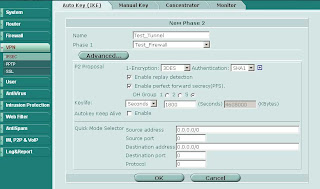
Start by building your site-to-site VPN tunnels in interface mode (see here for more info on interface mode). Important Note: Make sure your Phase 2 quick mode selectors are set to 0.0.0.0/0.
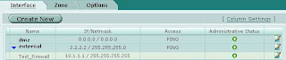
Once you have your tunnels configured go to Network -> Interface and expand the blue triangle next to the interface to which you have the tunnel attached:
Something which is not immediately obvious is that you can define an IP address on the tunnel interface. Edit the tunnel interface and assign unique IP addresses (i.e. something that is not in use on your network, typically a private IP) for the local and remote IP:
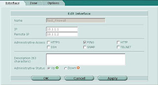
On the other side of the tunnel perform the same operation, reversing the settings for local and remote IP.
Now on to the OSPF side of things. Under Router -> Dynamic -> OSPF define Area 0.0.0.0 (the backbone). Then configure a Network which includes the network of the tunnel interface and place it in area 0.0.0.0. Under Interfaces create an interface tied to the tunnel interface. You can leave the IP as 0.0.0.0.
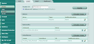
Repeat the same on the other end and you should see your routes starting to come in as OSPF dynamic routes. To control which routes are advertised you can redistribute networks under the Advanced Options in OSPF. You can also apply router access lists to filter networks from being advertised. More on router access lists (used for OSPF) and router prefix lists (used for BGP) in another post.
Start by building your site-to-site VPN tunnels in interface mode (see here for more info on interface mode). Important Note: Make sure your Phase 2 quick mode selectors are set to 0.0.0.0/0.

Once you have your tunnels configured go to Network -> Interface and expand the blue triangle next to the interface to which you have the tunnel attached:

Something which is not immediately obvious is that you can define an IP address on the tunnel interface. Edit the tunnel interface and assign unique IP addresses (i.e. something that is not in use on your network, typically a private IP) for the local and remote IP:

On the other side of the tunnel perform the same operation, reversing the settings for local and remote IP.
Now on to the OSPF side of things. Under Router -> Dynamic -> OSPF define Area 0.0.0.0 (the backbone). Then configure a Network which includes the network of the tunnel interface and place it in area 0.0.0.0. Under Interfaces create an interface tied to the tunnel interface. You can leave the IP as 0.0.0.0.

Repeat the same on the other end and you should see your routes starting to come in as OSPF dynamic routes. To control which routes are advertised you can redistribute networks under the Advanced Options in OSPF. You can also apply router access lists to filter networks from being advertised. More on router access lists (used for OSPF) and router prefix lists (used for BGP) in another post.
Labels:
dynamic routing,
fortigate,
ipsec,
ospf,
VPN
Saturday, March 22, 2008
Advanced IPSEC VPNs - Phase 2 Quick Mode Selectors
Most of the time when you create site-to-site VPN tunnels the Phase 2 Quick Mode Selector just doesn't cut it. In FortiOS 2.8 you were able to choose between manually entering source and destination addresses or selecting objects from a drop-down list. This feature is absolutely essential when creating VPNs that contain discontiguous subnets. A good example:
Source subnets: 172.16.1.0/24 and 192.168.1.0/24, destination subnets: 172.16.99.0/24 and 10.1.1.0/24.
In FortiOS 3.0 up to MR6 the drop-down option no longer exists in the GUI. However you can still pop the hood and get at the internals using the CLI. Here's how:

Source subnets: 172.16.1.0/24 and 192.168.1.0/24, destination subnets: 172.16.99.0/24 and 10.1.1.0/24.
In FortiOS 3.0 up to MR6 the drop-down option no longer exists in the GUI. However you can still pop the hood and get at the internals using the CLI. Here's how:
- In the GUI define the local and remote subnets for the VPN
- Group local and remote subnets into separate address groups (e.g. "encdom-local-remote" and "encdom-remote-local")
- On the CLI
- # config vpn ipsec phase2 (or #config vpn ipsec phase2-interface if you are using interface mode)
- # set src-addr-type name
- # set src-name encdom-local-remote (the address group containing your local subnets)
- # set dst-addr-type name
- # set dst-name encdom-remote-local (the address group containing the remote subnets)
- # end

Labels:
CLI,
interface mode,
ipsec,
VPN
Subscribe to:
Posts (Atom)